- Get link
- X
- Other Apps
If a mosfet synchronous switch were used instead of the diode even higher charge efficiency could be achieved. Capacitive charge pump circuits are used in many applications.

The Forever Rechargeable Variable Super Capacitor Battery

Dc Circuits Containing Resistors And Capacitors Physics

Lead Acid Battery Charger Circuit Diagram And Its Working
In this circuit the maximum battery current is limited by a resistor placed at the output of the dcdc converter.

Efficient capacitor charging circuit. Charging a capacitor means the accumulation of charge over the plates of the capacitor where discharging is a completely opposite process. Charging capacitors from a voltage source through a switch achieves maximum 50 efficiency wasting half of input energy in the switch. In this case the multiplication of both efficiencies gives the total efficiency for charging a capacitor from a sinusiodal grid voltage via an efficient constant current source.
6 efficient super capacitor charging with tps62740 slva678december 2014 submit documentation feedback. By analyzing the model of a basic charge pump circuit its possible to derive expressions for efficiency. Among their many applications capacitors are often used as short term energy storage elements in electronic systems.
For a 1 kw resistor and a 1000 uf capacitor the time constant should be 1 second. The diode is required in the inductive charge circuit to capture the peak resonant voltage on the capacitor. Suppose we have the circuit below with capacitor c voltage source v and a toggle switch.
Efficient charging the ltc3128 uses fixed frequency average input current pwm control when charging the output capacitors. The time constant t of a resistor capacitor circuit is calculated by taking the circuit resistance and multiplying it by the circuit capacitance. My statement is that this can be accomplished with a total efficiency of over 50.
And though these circuits appear deceptively simple engineers working on them need a thorough understanding of how they function. When a capacitor charges in a simple series rc resistor capacitor circuit the energy stored in the capacitor increases as it charges and the resistor dissipates energy as the capacitor charging current passes through it. A proprietary switching algorithm allows the charger to switch between buck and boost modes without discontinuity in inductor current or loop characteristics.
On the other hand charging capacitors with a current source can minimize the switching loss as the fixed charging current becomes smaller. Consider the capacitor is discharged initially and the switch is open. A schottky is used for better charge efficiency.
The tps62740 is able to set the output voltage according to the levels at the vsel pins in a resolution of 100 mv. As the inductor finishes charging the energy stored in the inductor can than be released ideally into the capacitor toward the end of the capacitor charging process where more energy is required to place charge on the capacitor. So both charging and discharging the inductor helps make the capacitor charging more efficient.

Tricky 12v Battery Charger Circuit

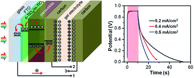
Integrated Perovskite Solar Capacitors With High Energy

Efficient Flyback Driver Circuit Using Ic 555

Specialized Charger Ics Manage Supercapacitors Digikey

Can I Charge A Ni Mh Battery Using A Standard Piezoelectric

Electronics Free Full Text Llc Resonant Converter For

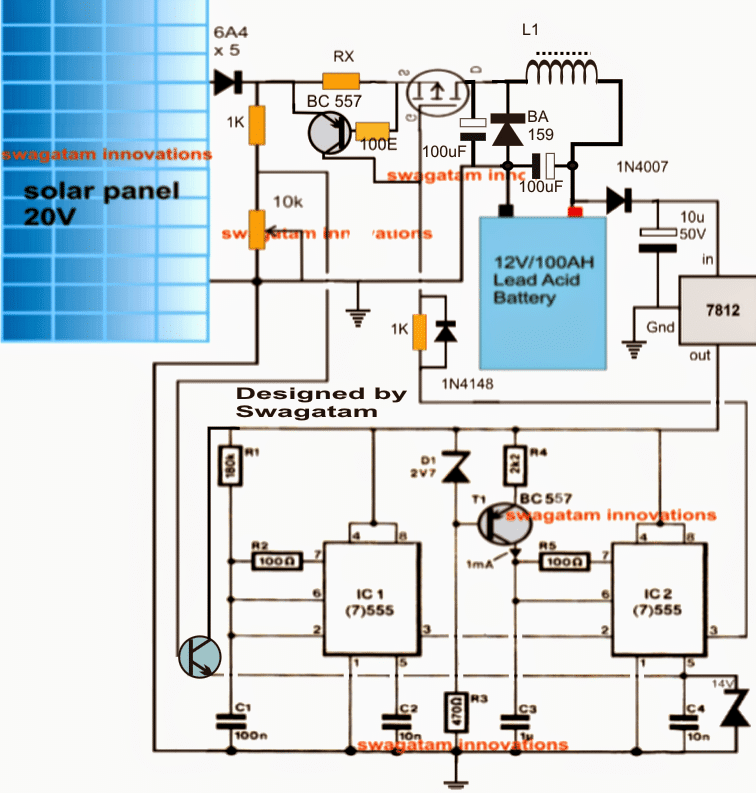
Self Optimizing Solar Battery Charger Circuit Homemade

Capacitor Charging And Discharging Dc Circuits

Jlpea Free Full Text A Performance Of The Soft Charging

High Voltage

Integrated Charge Excitation Triboelectric Nanogenerator

Wireless Mobile Charger Circuit Diagram Engineering Projects
- Get link
- X
- Other Apps
Comments
Post a Comment